- 您现在的位置:买卖IC网 > Sheet目录2000 > IDT82V3255TFG (IDT, Integrated Device Technology Inc)IC PLL WAN SMC STRATUM 3 64-TQFP
IDT82V3255
WAN PLL
Programming Information
109
December 3, 2008
6.2.10
SYNCHRONIZATION CONFIGURATION REGISTERS
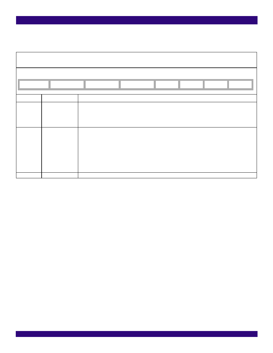
SYNC_MONITOR_CNFG - Sync Monitor Configuration
Address:7CH
Type: Read / Write
Default Value: 00101011
Bit
Name
Description
7
SYNC_BYPASS
This bit selects one frame sync input signal to synchronize the frame sync output signals.
0: EX_SYNC1 is selected. (default)
1: When the T0 selected input clock is IN1_CMOS or IN1_DIFF, EX_SYNC1 is selected; when the T0 selected input clock
is IN2_CMOS or IN2_DIFF, EX_SYNC2 is selected; when the T0 selected input clock is IN3_CMOS, EX_SYNC3 is
selected; when there is no T0 selected input clock, no frame sync input signal is selected.
6 - 4
SYNC_MON_LIMT[2:0]
These bits set the limit for the external sync alarm.
000: ±1 UI.
001: ±2 UI.
010: ±3 UI. (default)
011: ±4 UI.
100: ±5 UI.
101: ±6 UI.
110: ±7 UI.
111: ±8 UI.
3 - 0
-
These bits must be set to ‘1011’.
7
6
5
4
3210
SYNC_BYPASS
SYNC_MON_LIMT2
SYNC_MON_LIMT1
SYNC_MON_LIMT0
-
发布紧急采购,3分钟左右您将得到回复。
相关PDF资料
IDT82V3280APFG
IC PLL WAN SE STRATUM 2 100TQFP
IDT82V3285AEQG
IC PLL WAN SE STRATUM 100TQFP
IDT82V3285EQG
IC PLL WAN SE STRATUM 100TQFP
IDT82V3288BCG
IC PLL WAN 3E STRATUM 2 208CABGA
IDT82V3355EDG
IC PLL WAN SYNC ETHERNET 64TQFP
IDT82V3358EDG
IC PLL WAN SYNC ETHERNET 64TQFP
IDTCSPT857DNLG8
IC PLL CLK DVR SDRAM 40-VFQFPN
IDTCV105EPVG8
IC CLK GEN DESKTOP PC 48-SSOP
相关代理商/技术参数
IDT82V3255TFG8
功能描述:IC PLL WAN SMC STRATUM 3 64-TQFP RoHS:是 类别:集成电路 (IC) >> 时钟/计时 - 专用 系列:- 标准包装:1,500 系列:- 类型:时钟缓冲器/驱动器 PLL:是 主要目的:- 输入:- 输出:- 电路数:- 比率 - 输入:输出:- 差分 - 输入:输出:- 频率 - 最大:- 电源电压:3.3V 工作温度:0°C ~ 70°C 安装类型:表面贴装 封装/外壳:28-SSOP(0.209",5.30mm 宽) 供应商设备封装:28-SSOP 包装:带卷 (TR) 其它名称:93786AFT
IDT82V3255TFGBLANK
制造商:IDT 制造商全称:Integrated Device Technology 功能描述:WAN PLL
IDT82V3280
制造商:IDT 制造商全称:Integrated Device Technology 功能描述:WAN PLL
IDT82V3280_08
制造商:IDT 制造商全称:Integrated Device Technology 功能描述:WAN PLL
IDT82V3280APFG
功能描述:IC PLL WAN SE STRATUM 2 100TQFP RoHS:是 类别:集成电路 (IC) >> 时钟/计时 - 专用 系列:- 标准包装:1,500 系列:- 类型:时钟缓冲器/驱动器 PLL:是 主要目的:- 输入:- 输出:- 电路数:- 比率 - 输入:输出:- 差分 - 输入:输出:- 频率 - 最大:- 电源电压:3.3V 工作温度:0°C ~ 70°C 安装类型:表面贴装 封装/外壳:28-SSOP(0.209",5.30mm 宽) 供应商设备封装:28-SSOP 包装:带卷 (TR) 其它名称:93786AFT
IDT82V3280APFG8
制造商:Integrated Device Technology Inc 功能描述:IC PLL WAN SE STRATUM 2 100TQFP
IDT82V3280DQ
制造商:IDT 制造商全称:Integrated Device Technology 功能描述:WAN PLL
IDT82V3280DQG
功能描述:IC PLL WAN SE STRATUM 2 100-TQFP RoHS:是 类别:集成电路 (IC) >> 时钟/计时 - 专用 系列:- 标准包装:1,500 系列:- 类型:时钟缓冲器/驱动器 PLL:是 主要目的:- 输入:- 输出:- 电路数:- 比率 - 输入:输出:- 差分 - 输入:输出:- 频率 - 最大:- 电源电压:3.3V 工作温度:0°C ~ 70°C 安装类型:表面贴装 封装/外壳:28-SSOP(0.209",5.30mm 宽) 供应商设备封装:28-SSOP 包装:带卷 (TR) 其它名称:93786AFT